SolidWorks: Cut-Extrude Advanced Technique
Cut features are a very important part of designing. We have covered the cut extrude basics in a previous blog that can be found here. This blog will be going over some of the more advanced settings and cutting features like swept cuts, revolved cuts, and lofted cuts. Sign up for our newsletter to stay up to date on new content from our team!
Extrude Cut - Thin Feature
The “Thin Feature” option in most feature managers is often overlooked. When used correctly, this option can save you quite some time. Thin features often use open sketches but can also use closed sketches. The thin features option gives the sketch a cut thickness and an extrusion depth as seen below in figure 1.
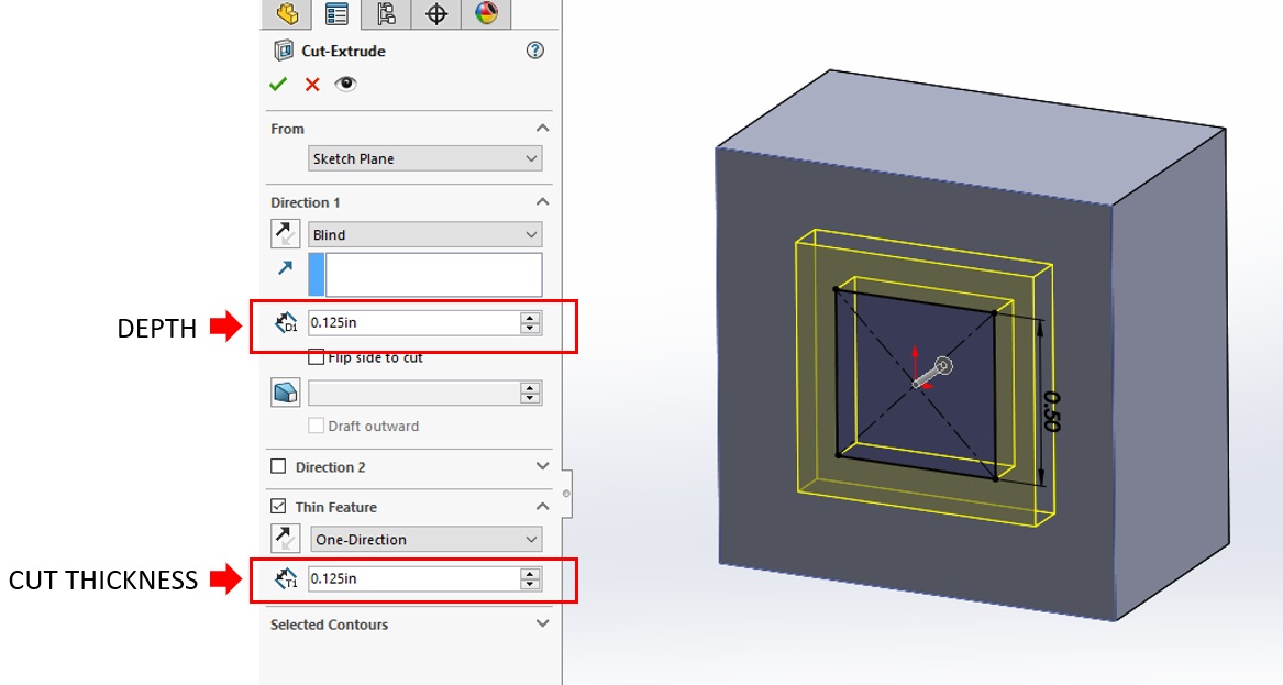
Figure 1: Thin feature cut thickness
The thin feature allows you to cut in one direction, from the midplane, or in two separate directions. Cutting in one direction allows you to cut to either side of the sketch at a determined distance. Cutting from the midplane will allow the cut to be spaced equally on both sides of the sketch. And Cutting in two separate directions will allow you to cut a specified distance from both sides of the sketch. Check out the examples below on cut directions in Figure 2.

Figure 2: Thin feature cut directions
Extruded Cut - Flip Side to Cut
The “flip side to cut” option is not used very often. Most designers overlook this or have no idea what it does exactly. The flip side to cut option works with a sketch profile and whatever face that sketch lays on. When this option is selected the entire face area outside of the sketch on that face is selected as the cutting boundary. For example, if you place a square sketch on a square surface and use the flip side to cut option, the area around the square sketch will be cut back and it will look as if you have just used an extrude feature on your sketch. Check out the example images below in Figure 3 to get a better idea of how the flip side to cut option works.

Figure 3: Flip side to cut vs. regular cut
As you can see in the example the same sketch was used on the same surface. The flip side to cut simply selects the area outside of your sketch profile and cuts that area instead. The flip side to cut selection box can be found in the extrude cut feature manager right below the cut depth value box. See Figure 4 below to view the location of the flip side to cut option.

Figure 4: Flip side to cut option location
Revolved Cuts
There are many powerful cutting tools within SolidWorks besides the basic extrude cut tool. The revolved cut tool allows you to cut a profile around an axis creating complex geometry in a single feature. To set up a revolved cut it is very similar to any other feature, you start with a sketch. See Figure 5 below to find the location of the revolved cut tool.

Figure 5: Revolved cut feature location
Ideally, for revolved cuts, you will be sketching on a center plane within the part to have the cut be equal all the way around the part. In the sketch you must create an axis to revolve the cut around, this can be a sketch line or a construction line. After you have created an axis you can create the profiles you wish to revolve. Check out my example sketch below in Figure 6.

Figure 6: Example revolve cut sketch
Once you have your sketch set up you are ready to revolve! Select the revolved cut feature from the toolbar. The feature manager will ask you to select an axis of revolution, this will be the axis you created in your sketch. Once the axis is selected, typically, the rest of your sketch profile will be selected at the contours to cut but if they do not auto select, open up the selected contours option and manually select which sketch contours you would like to use to cut. Once you have made all your selections hit that green check and you have just completed a revolved cut! See Figure 7 below for an example of what is selected within the feature manager for the revolved cut.

Figure 7: Revolved cut feature manager
Lofted Cuts
A lofted cut is a feature that removes material between two sketch profiles. To complete a lofted cut, you must create a minimum of two separate sketches on your part that you wish to cut between. Once you have created your two sketches, you are ready to cut! Figure 8 below shows the location of the lofted cut tool on the SolidWorks toolbar.
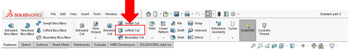
Figure 8: Lofted cut feature location
As you can see in my example below in Figure 9, I have created two separate sketches on opposite sides of the cube to achieve an angled cut through the center. Once you have the lofted cut feature manager open, go ahead and select each of the two sketches you would like to use in the lofted cut. Make sure your selections are under the profiles selection box and not the guide curves selection box. Once you have your profiles selected hit the green check and the lofted cut is complete!

Figure 9: Lofted cut example
Swept Cuts
A swept cut allows you to cut a model by sweeping a closed profile sketch along a path sketch. Swept cuts are great for making organic-looking cuts in geometry. In order to complete a swept cut, you must have a minimum of two sketches. One sketch will be the profile sketch, and this will be the outline of the cut. The second sketch needed will be the path sketch. The path sketch will control the direction of the cut. Figure 10 below shows the location of the swept cut tool.

Figure 10: Swept cut feature location
As you can see in the example image below, I have decided to do a circular profile cut along a curvy path. I created the sketch path first on the face of the block. When creating the secondary profile sketch I was able to make relations between the two sketches and have them connect. If the profile sketch is not connected to the path sketch, the swept cut operation will not work.

Figure 11: Swept sketch profiles
Once you have your sketches laid out and you are ready to cut, click on the swept cut feature to open the feature manager. The first selection box will ask you to select the cut profile, in the case of this example, this will be the circular sketch profile I have created. The second selection box will ask you to select the path sketch. Once both sketches are selected you will see a preview of the cut. If all looks good, click on the green check to complete your swept cut! See figure 12 below for a look into the swept cut feature manager.

Figure 12: Swept cut feature manager
Conclusion
SolidWorks offers many different and powerful tools for cutting 3D geometry and models. This blog was a quick overview of the more advanced cutting techniques that are available.
Thanks for reading! Whether you have questions or need our contract services, please don't hesitate to contact us!