Design for Speed - Tips and Tricks
Design for Speed – Tips and Tricks!
As a CAD designer speed is very important. You need to be as efficient as possible when working on designs to stay on budget and ahead of deadlines. Now, SolidWorks is a large program and there are a lot of things you need to know and be proficient in to be efficient when designing. First things first, proper design intent is essential. Ensuring that you have thoroughly considered how to create your initial sketch and features can save you significant time, not only when it comes to the original design, but potentially any future changes as well. So, once you have that mastered, how can you cut even more time off your designs? Let us teach you some simple tips and tricks that are guaranteed to take your design speed up a notch
Graphics Options
When it comes to designing, you can only be as fast as your computer. Historically, SolidWorks has taken up primarily a lot of CPU usage. Even with proper GPU installed in a computer, the CPU was often a bottleneck, preventing the GPU from even reaching its full potential. This can cause slow loading and small pauses often. Starting in 2019, SolidWorks released a new graphics engine based on OpenGL 4.5 graphics. This allowed the GPU to be better utilized and freed up the CPU, ultimately increasing the speed when working in SolidWorks. That being said, not everyone has the opportunity to purchase high-end GPU units. Thankfully, there are some graphical options we can adjust to help increase our computer speed when running SolidWorks. Click on the systems option icon and open the performance menu, see the image below for location.

Image 1: System options and performance menu locations
At the bottom of the performance menu click on the “Go to Image Quality” button. From here you have the ability to adjust the resolution of your models. The resolution plays a big role in how fast your computer can run SolidWorks so try adjusting the slide bars to show a lower resolution. You will notice that the curved areas of your model become blockier and flatter, but this is simply just the graphics and that edge still holds the same curved size/dimension as it previously did. You may notice a section of red at the far right of the slider. As you increase the resolution to a high enough point this will require a lot of computing power. This red zone indicates a high potential of slowing your computer down. Now, while there is not any red to the far left, there should be some caution in going too far in that direction as well. By decreasing the resolution by so much, you end up with such a blocky model that it can be hard to tell visually if something is wrong. This increases the potential for errors.

Image 2: Resolution options
The purposes for each of the settings can be found below.
Shaded and draft quality HLR/HLV resolution – This slider allows you to control the resolution of curved surfaces. This option is only available in assemblies if the Apply to all referenced part documents is selected.
Deviation – This option is inversely tied to the slider and allows you to type in a custom number. It represents the maximum chordal deviation.
Optimize edge length (higher quality, but slower) – This will allow you to increase the quality of the image even further if you have already maxed out the slider to the right. Keep in mind that this will slow your system even further and cause increased file size.
Apply to all referenced part documents – This setting is for assemblies only and will be greyed out for parts. By selecting this option, you will apply the current settings to all the child parts within the assembly.
Save tessellation with part document – This setting is for parts only and will be greyed out for assemblies. This option allows the system to save the display information, which allows for viewing with view-only mode, SolidWorks Viewer, and eDrawings. By clearing the display data, you can often significantly reduce file sizes.
Wireframe and high-quality HLR/HLV resolution – This slider allows you to control the resolution of model edges in parts and drawings
Precisely render overlapping geometry (higher quality, but slower) – This option is only available for drawing documents. If there are a significant amount of small intersections in your drawings, you can increase your performance by clearing this option.
Use isometric, zoom-to-fit view for document preview – This creates a standard preview, that you would see in your file explorer for example, in which your file is in an isometric view and zoomed to fit. If cleared, the last saved view will be displayed.
Use pre-2009 tangent edge definition – When selected, all tangent edges will appear in your model. When cleared, tangent edges between two faces that have an angle between them of less than one degree will not appear.
S Key
Setting up your S key for shortcuts can be a lifesaver when it comes to design time. When you push your S key a small menu will open right next to your cursor. This menu can be customized to hold several features that you use frequently. Using the S key will save you the time it takes to move your cursor to the upper toolbars and have to search for that feature. Now that may seem like it would only save you seconds but in the long run, using the S key could save you countless hours.
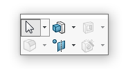
Image 3: S Key menu
To customize your S key menu, go up to the “Tools” dropdown menu and click on “Customize”. Once you are in the customize menu click on the “Shortcut Bars” tab. From here you can drag and drop any feature or tool you would like onto your S key menu. There is no limit to the number of items you can place on your S key menu. The S key is mode specific meaning you can have different S key menu setups for when you are in a part file, an assembly file, a drawing file, or when you are within a sketch. Take some time to look through the possible features and set up your S key for each mode!

Image 4: Shortcut customization location
Below you will find a basic setup for each of the four shortcut toolbars.

Image 5: Shortcut Toolbar Customizations
You can implement these into your current modeling process or use them as a starting point and modify them as needed. As you are moving into more advanced modeling, you can even set up a toolbar for each type of modeling you work with. For example, if you would like to have quick access to certain tools when you are working primarily with surfaces or weldments, you can set up a toolbar for each of these, save the SolidWorks settings, and load those settings whenever you are completing that type of work.
Mouse Gestures
Mouse gestures are very similar to the S key but only require one click of the mouse. They can also be set up to work in tandem with your S key shortcuts. Mouse gestures are usually turned on by default and can be accessed by clicking and holding the right mouse button and then slightly dragging the mouse. If you do not have your mouse gesture enabled, you can go to the “Tools” dropdown menu and click on “Customize” then select the “Mouse Gestures” tab where you will find an enable selection box.

Image 6: Mouse gesture customization menu
Mouse gestures are similar to the S key in a way that they are both mode specific meaning you can set up your gestures for part files, assembly files, drawing files, and within a sketch. The mouse gestures are displayed on a wheel and you are only allowed a limited number of features on the wheels. You can have either 2, 3, 4, 8, or 12 features present on your gesture wheel. Customizing your wheel is easy as you can simply search for a feature and then drag and drop it onto whichever wheel you want within the customization window. As I said earlier these mouse gestures can be used in tandem with your S key menu so spend some time setting up both in a way that will give you maximum efficiency!
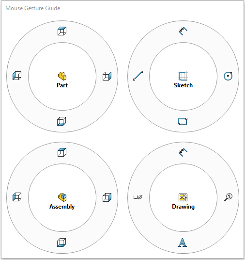
Image 7: Mouse gesture wheels
Detailing Mode
If you have spent much time creating drawings for large assemblies in SolidWorks, you know how painful it can be to load up the drawing pack, which requires the loading of the entire assembly to the memory, all to make a quick change. SolidWorks 2020 introduced a new feature known as Detailing Mode. By opening a drawing in Detailing Mode, you are able to complete tasks such as adding leaders annotations such as notes, leader notations such as weld callouts, and more. This does have limitations. For example, you cannot create new dimensions unless it is to sketch geometry, otherwise you would have to resolve the drawing to proceed. This provides a great way to save time when quick changes are needed to a drawing packet!
Conclusion
SolidWorks offers several ways to improve your overall design speed. These are only a few of the many tips and tricks that can help you improve your design speed.
Feel free to contact us if you have any questions or if you require our contract services! Thanks for reading our blog!