SolidWorks: Threading
The threading feature in SolidWorks offers you a much easier way to create threaded feature geometry on your parts. Previously you would need to sketch out the profile of your thread and the pitch with a helix. Now adding threads is as simple as a few clicks. This blog will review the thread feature and show you how to utilize this helpful tool in your designs!
Feature Location
If you have never used the thread feature it may be quite hard to find. You can easily find it using the search bar under the commands filter by typing in “thread” and selecting the tool. The feature can also be found in the drop-down menu that is attached to the hole wizard feature. Check out the image below to see where you can find the thread feature.
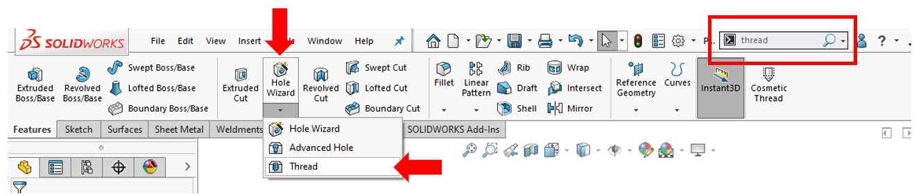
Figure 1: Thread Feature Location
Applying Thread Feature to Parts
To apply thread features to your part you will first need a cylindrical surface. The thread feature allows you to both extrude threads and cut threads so this cylindrical surface can be the inside of a hole or the outside surface of a shaft. For my example, I have a simple hex bolt that we will be cutting threads into.

Figure 2: Cylindrical Surface Example
Thread Feature Manager
Once you open the thread feature manager it will first ask you for an edge of a cylinder where you would like to start your threads. Select your starting edge and a preview of the threads will appear. A pink thread preview shows cut threads while a green thread preview will show extruded threads. There is also a selection box that allows you to pick a vertex, edge, or plane for your starting point if you would like. You are also given the ability to offset your threads and change the start angle. All of these options are in the first portion of the feature manager.
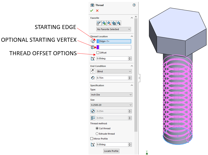
Figure 3: Feature Manager Starting Options
End Conditions and Specifications
After you have selected your starting point and any offsets, you now select how far you want your threads to extend up the shaft. You are given three end condition options. You can select blind, which allows you to input any dimension for how far up the shaft you want the threads to extend. You can select revolutions, which will control the distance of the thread based on the input number of revolutions also driven by the pitch of the thread selected. The final selection is up to selection, which allows you to select other geometry on your model and the threads will run up to that selected face or feature.

Figure 4: End Condition Options
The most important part of this feature is selecting the correct thread type and size. Under the Specification drop-down, you are given the option between inch tap/dies and metric tap/dies. After making your unit selection the second drop-down list will offer you all the thread sizes available. For my example, I will be using an inch die and ¼-20 threads to cut into the ¼” shaft. After selecting your sizes you do have the ability to override the set parameters if you so choose to. Below this, you are given the selection options to either cut or extrude your threads. There is also an option to mirror your threads over the edge that was selected and an angle selection box that allows you to rotate your threads. For my example, none of the parameters were changed and no rotation was applied to the threads.

Figure 5: Specification Options
Further Thread Options
Near the bottom of the thread feature manager, you will find some further customization options. You can select if you would like your threads to be left-handed or right-handed threads. There is a multiple start option that will allow multiple instances of the same thread to be cut into the same face. This would be done to give the threads two start points instead of one for ease of use. The final two options are to trim with the start and end face. These options will cut the profile of the thread off once it passes the start or end point so it will not cut into the wrong geometry. After you have made your final selections click the green check-mark to make your threads!

Figure 6: Finished Thread Example
Conclusion
The thread tool in SolidWorks is incredibly powerful and can save you large amounts of time. Previously, making threaded features was tedious and complicated but now you can create complex threaded geometry with just a few clicks!
Please do not hesitate to get in touch with us if you have any questions or are in need of contract services. We are always here to help!